Place the part
The operator places the part in the defined work area. The target system detects its presence and begins preparing the cycle once safety conditions are met.
 PRISMATEC.APP
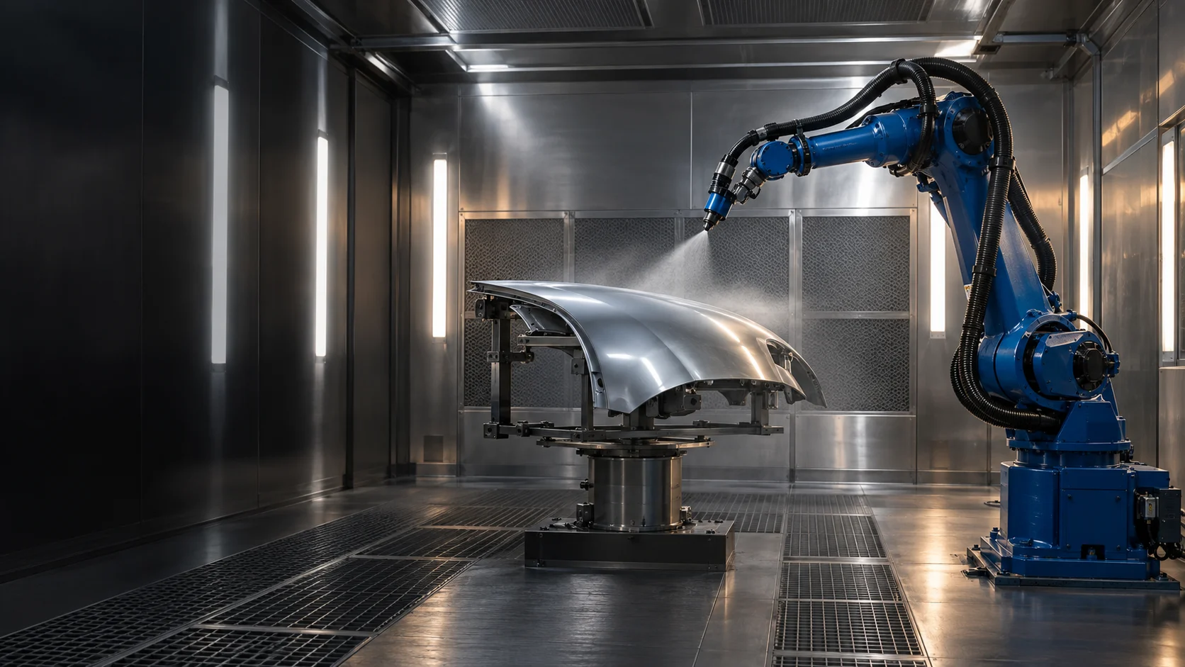
PRISMATEC / SCAN2SPRAY
SCAN2SPRAY brings part geometry, path planning and coating simulation into one environment. The process, fixtures and robot integration are configured for a specific part family and production workflow.
ENGINEERED BY ABLATHERM AEROSPACE
01 / SCAN2SPRAY
In developmentSCAN-DRIVEN AUTOMATION
CAD-BASED PLANNING
THE INDUSTRIAL CHALLENGE
With changing geometries and short production runs, programming, spray-strategy selection and process trials become a significant part of deployment effort. SCAN2SPRAY aims to move more decisions into the digital environment and make approved process knowledge reusable.
Shared tools cover CAD surface selection, spray parameters, paths, successive layers and coating assessment. The guitar example shows one configuration; other part families require their own strategy, fixtures and calibration.
Explore features and applications →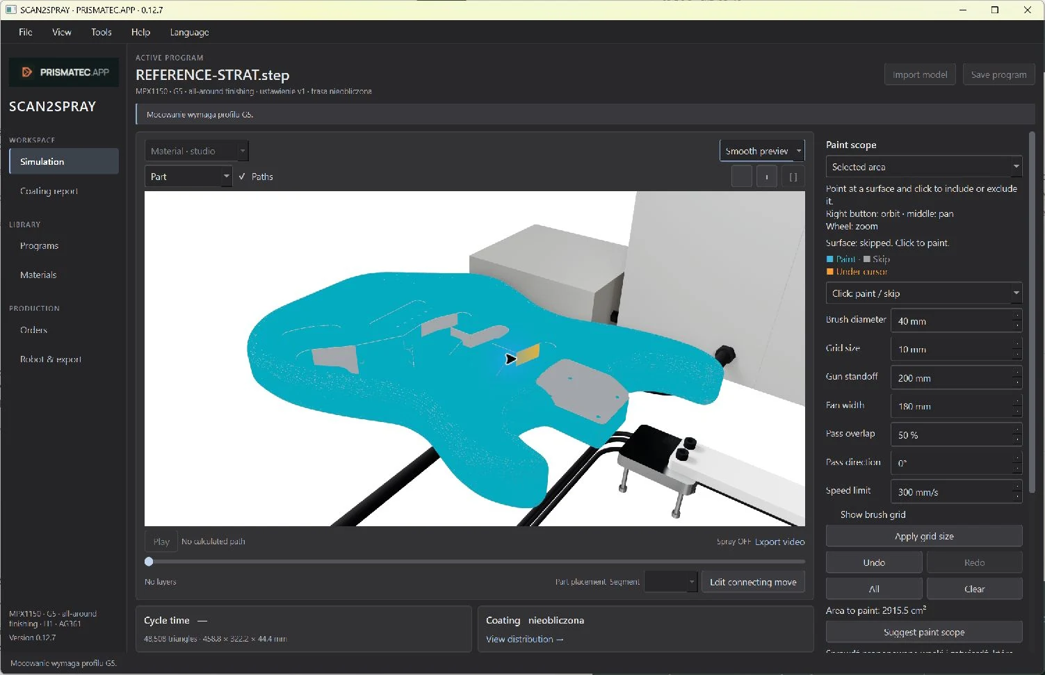
SOFTWARE / FEATURES / APPLICATIONS
Explore surface selection, spray settings, heatmaps and reports. Guitar finishing demonstrates one configuration of the shared platform.
Explore features and applications ↗02 / SCAN2SPRAY — SCAN TO FINISH
We are working towards fully automated painting: once a part is placed on the table, the system is intended to acquire a 3D scan, build its geometry, prepare and verify the strategy, then carry out spraying and record the process outcome.
This scene illustrates the process. The current table design and calculated robot paths are available in a separate preview.
Open the current cell simulation
Process visualization • illustrative motionDrag to orbit the cell.
Coverage & feasibility review
Geometry / Plan / Parameters / Events
Loading the 3D scene…
The operator places the part in the defined work area. The target system detects its presence and begins preparing the cycle once safety conditions are met.
The 3D scanner is intended to capture the actual shape and position directly in the cell. In this mode, geometry is built from the current measurement, without requiring a pre-prepared CAD model for every new part.
From the point cloud, the system is intended to reconstruct surfaces, define coating regions and identify features relevant to application. Development includes scan-completeness assessment and geometry handling within a qualified application range.
Geometry and material requirements drive strategy selection, applicator orientation, passes and dose. The existing planning engine provides the foundation for the developing scan-to-execution workflow.
Before execution, the system is intended to check modelled coverage, motion feasibility, cell constraints and cycle-start conditions. An incomplete scan or an out-of-range plan requires preparation to stop and the issue to be resolved.
Once the conditions are approved, the robot and applicator are intended to execute the plan automatically in the calibrated cell frame. The goal is to move from a placed part to a painted part without manually programming each cycle.
The plan, parameters, timings and events are intended to form a process history. Planned SmartBooth connectivity will link execution to an order and provide production reports and data for further improvement.
CAD + scan localization: prepare and reuse a plan for a known part. Scan → geometry → plan: the target adaptive mode for a part measured in the cell. We are developing both directions; the automation scope will be validated progressively on real parts.
LATER STAGE / AI & NEURAL NETWORKS
We plan to use AI and neural networks to improve the selection of strategies, parameters and technical solutions. Geometry, material, plan and actual outcome data are intended to help compare decisions and improve subsequent processes.
Learning will require trial data and coating measurements, model validation and controlled deployment of changes within permitted process limits.
Data → learning → validation → better process selection03 / BUSINESS PERSPECTIVE
A development direction for manufacturers, integrators and investment partners.
The aim is to reduce repetitive programming work by generating and comparing strategies in one environment.
Versioned plans, parameters and results provide a foundation for reusing knowledge instead of starting each series from scratch.
Project outcomes should be assessed through preparation time, coating quality and uniformity, material consumption and repeatability for a selected family of parts.
Jobs, parts, scenarios, plan generation, 3D review, coverage assessment and versioned outputs. Algorithms are being developed and checked through software tests.
Calibration, scan-based localization, robot program export and execution, and communication with process equipment.
A selected part family, agreed acceptance criteria and comparison against the baseline process. Actual economic impact can only be established through measurement.
We welcome discussions about a pilot cell, technology integration and project development. The starting point is a specific part, a process and a jointly agreed validation scope.
Discuss a partnership04 / PRISMATEC CONTROL
Prismatec Control brings together industrial booth control, local AI processing, an operator panel and a data layer. The v2.0 architecture under development comprises PLC control, an AI Edge vision module, HMI and remote diagnostics and telemetry services.
PRISMATEC CONTROL
We are developing a shared control platform for booth manufacturers, integrators and industrial users. An implementation has already been completed for the TECNOVA brand. Further implementations can be developed with other manufacturers, configured for their equipment and processes.
SEE HOW THE BOOTH INTERPRETS AN IMAGE
Choose an example and follow the path from an image to a control response. This is the direction of Prismatec Control vision: supporting the operator, process quality and the history of every job.
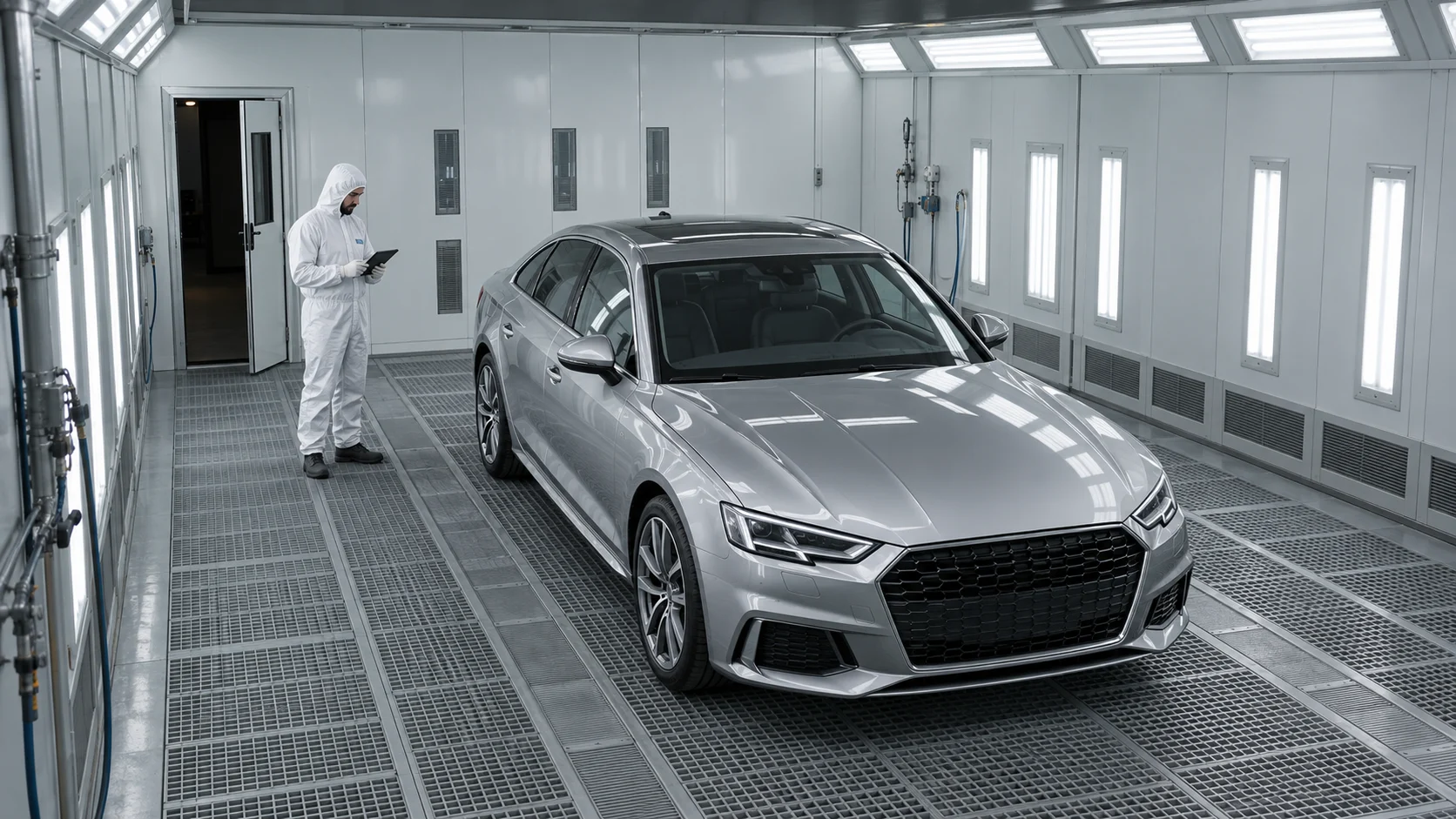
 ILLUSTRATIVE EXAMPLE
A car is inside the booth working area.
A YOLO detector locates the vehicle in the image. A separate OCR module can read its licence plate.
The goal is to link the booth cycle to a SmartBooth job through confirmed identification. Times, parameters and events will enrich a shared history.
Less manual assignment of data to jobs.
A painter is beside the vehicle inside the booth.
YOLO detects the person. Tracking across frames helps establish presence and movement in a defined zone throughout the process.
Example: occupancy is checked before drying. The PLC combines this information with sensors and interlocks. Unmet conditions prevent startup; an event during a cycle triggers the designed protective response.
Supervision of the interior during operation, too.
The service door remains open.
A model trained for the installation can recognize doors and their state. This complements the physical door-closed sensor.
The controller checks required inputs. If a mode requires closed doors, it explains the interlock and prevents startup. The event can be recorded in the process history.
A clear interlock reason helps the operator respond.
A thermal camera shows surface temperature distribution. An ordinary RGB camera does not measure temperature by itself.
Planned analysis compares regions and heating over time: where the part heats more slowly and where local deviations appear. Measurement requires calibration and allowance for emissivity and reflections.
The goal is to support drying assessment, deviation detection and settings within an approved recipe. Temperature history and events will enrich the report. Thermal imaging alone does not confirm coating cure.
More insight into the part than air temperature alone.
YOLO is a family of neural networks. It learns from labelled images, then identifies object classes, locations and confidence in a new image. A box means “there is a person here” or “there is a vehicle here”. Motion tracking and OCR are further analysis modules.
Analysis is designed to run locally on an AI Edge computer such as NVIDIA Jetson. The PLC controls the process, the HMI explains status to the operator, and SmartBooth integration is intended to organize job data. Protective functions do not depend on cloud availability.
These examples show the development direction. Recognition requires installation-specific data and testing. AI supports supervision; protective responses also rely on sensors, interlocks and validated control logic.
TECHNOLOGY SCOPE & V2.0 DEVELOPMENT DIRECTIONS
Preparation, spraying, flash-off, drying and cooling. Temperature, supply/exhaust ventilation and booth-pressure regulation, with recipes, alarms and operator supervision.
Local image analysis on the NVIDIA Jetson platform. Development covers detection of people, door state, hoses, smoke and fire, plus recognition of vehicles and objects inside the booth.
Safety logic combines vision signals with door interlocks, emergency stop and required installation sensors. A missing required input must inhibit startup or lead to a safe state. These decisions do not depend on cloud availability.
Development aims include adaptive ventilation and drying parameters, energy-saving modes and energy-use analysis. Predictive models are intended to support settings appropriate to the coating and process conditions.
The operator interface presents states, parameters, cycle progress and alarms. Planned multilingual voice interaction is intended to simplify work while routing commands through the same permission and startup-condition logic.
Event history, telemetry and predictive diagnostics under development support service and deviation analysis. The v2.0 architecture includes device identity, software signing and European hosting of data services.
From preparation and spraying through flash-off and drying to cooling. Temperature, ventilation and pressure control work with the recipe and interior supervision. Each stage has startup conditions, parameters and events that can be traced.
Occupancy, door state and installation signals matter after startup, too. The control logic under development responds to changing conditions during operation. The operator should see what happened, when and why the process requires attention.
The development direction combines air temperature, thermal surface imagery and cycle history. Analysis is intended to detect uneven heating and support time, temperature and ventilation settings. Settings remain tied to the approved coating process.
Cycle stages, parameter trends, alarms and available consumption data form a basis for diagnostics. Planned SmartBooth integration will link this information to a job and SCAN2SPRAY data to robotic painting execution. One history instead of separate records.
PARTNERSHIP MODEL
Prismatec Control follows a licensing model: the partner builds and delivers the equipment while the platform provides a common software layer. Cooperation is not limited to one booth brand. Hardware integration, feature scope and implementation responsibilities are agreed for each installation.
Each unit has its own identity, partner and configuration assignment, and signed activation. This underpins management of installations, entitlements and software versions. Commercial terms are agreed with the partner.
The architecture defines Standard, Professional and Aerospace configurations on a shared codebase. Equipment, modules and process requirements determine implementation scope. A configuration name does not imply certification or identical features in every booth.
Digital signatures allow a device to verify package origin and integrity. Connect services develop activation, device status and diagnostics. Licensing must not disable protective functions of an operating installation; safety stays local.
The completed implementation provides a reference point for developing Prismatec Control as a standalone product. The scope of an individual installation is separate from the full platform roadmap.
The new architecture includes modules being developed and tested for cycles, regulation, safety conditions, device identity and licensing. Simulation checks full cycles and fault responses before hardware testing.
Next stages include validating AI and thermal imaging on installations, developing the operator interface and connecting SmartBooth. Neural networks are intended to learn from process data to better support settings, diagnostics and deviation prediction.
Function scope depends on configuration, equipment and deployment stage. AI supports supervision; protective functions require appropriate installation engineering and validation in the cell.
Implementation example for TECNOVA05 / ONE DATA ECOSYSTEM
We are connecting control, robotics and paint shop management. The goal is for every process to leave a structured data trail in SmartBooth.
PLANNED CROSS-PRODUCT INTEGRATION
Object identity · booth parameters · cycles · alarms
Geometry · plan version · execution · process data
Order · history · reports · operational analysis
In the target workflow, vision can identify a vehicle and read its licence plate, while integration links the cycle to the relevant SmartBooth order. Timings, parameters and booth events will enrich the execution history.
SCAN2SPRAY is intended to report the part identifier, plan version, execution history and available process data to SmartBooth. A shared order context will connect robot work, the booth cycle and the production report.
Licence-plate recognition and shared reporting represent target integration scenarios. Automatic assignment will require confirmed identification, permissions and configured data exchange.
SCAN2SPRAY brings part geometry, path planning and coating simulation into one environment. The process, fixtures and robot integration are configured for a specific part family and production workflow.
Explore the projectTECNOVA SmartBooth™ is a paint shop management application: vehicle and part orders, paint inventory and consumption, environmental records for PL / AT / DE, colour recipes and equipment status monitoring.
Organisation of paint shop work and operational data. Equipment data availability depends on the connected installation.
Visit the projectPrismatec Control brings together industrial booth control, local AI processing, an operator panel and a data layer. The v2.0 architecture under development comprises PLC control, an AI Edge vision module, HMI and remote diagnostics and telemetry services.
Explore the project06 / TECHNICAL QUESTIONS
CAD + scan localization: prepare and reuse a plan for a known part. Scan → geometry → plan: the target adaptive mode for a part measured in the cell. We are developing both directions; the automation scope will be validated progressively on real parts.
The model helps compare alternatives and identify planning issues. It does not replace actual coating measurements, applicator calibration or material trials. Parameters and acceptance criteria must be established for the specific process.
Use the form to describe your part, substrate, coating, expected batch size and available cell. This provides the basis for discussing project fit and the scope of further work.
07 / CONTACT & PARTNERSHIPS
Manufacturer, integrator or investment partner — tell us about your application or partnership idea. Let us discuss the technology, a pilot and project development.
Please use the contact form to get in touch.
We will reply to the email address you provide.